A self-driving, open-air rope-climbing gondola that carries six Playmobil passengers up a 30° incline, pauses at two intermediate tape markers, holds at the top, and returns to the start on its own — built around a dual-wheel friction drive and an Arduino IR control system, all under a 1 lb weight limit.
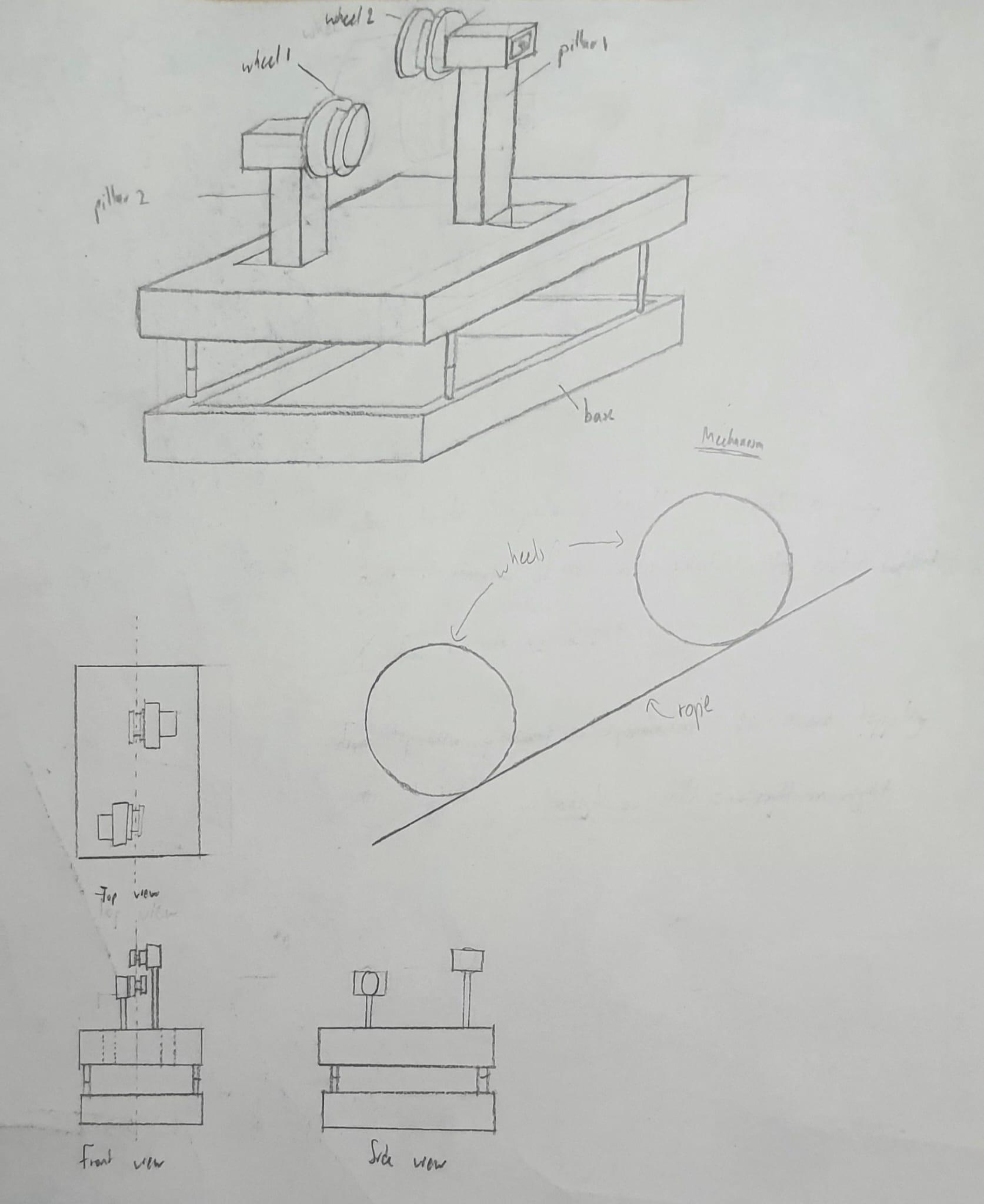
The goal was to replicate a full-scale ropeway in miniature: an open-air carriage that climbs an inclined rope, carries six passengers, makes timed stops, and returns to its start — entirely on its own and within a strict 1 lb weight budget.
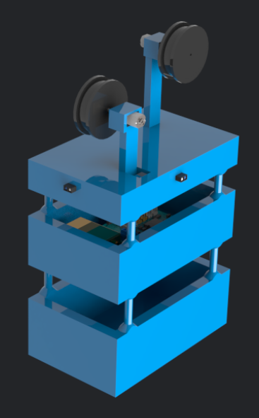
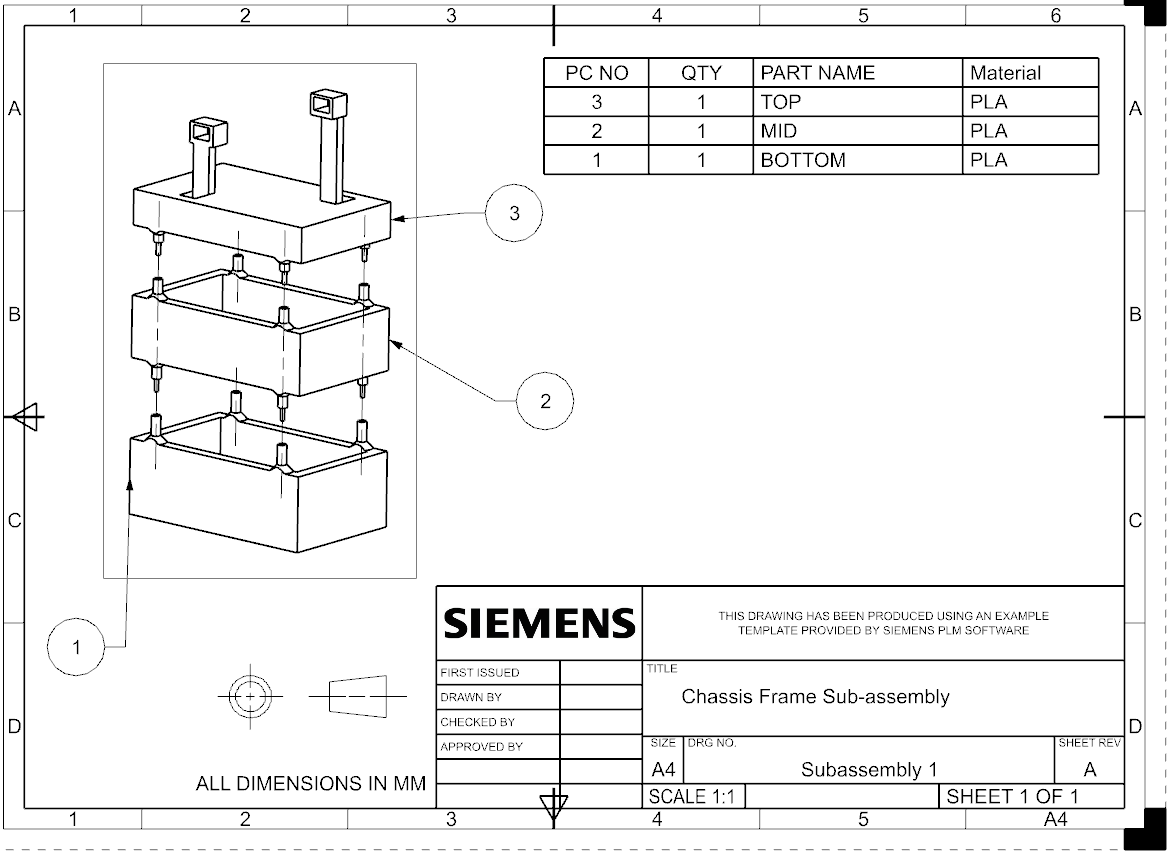
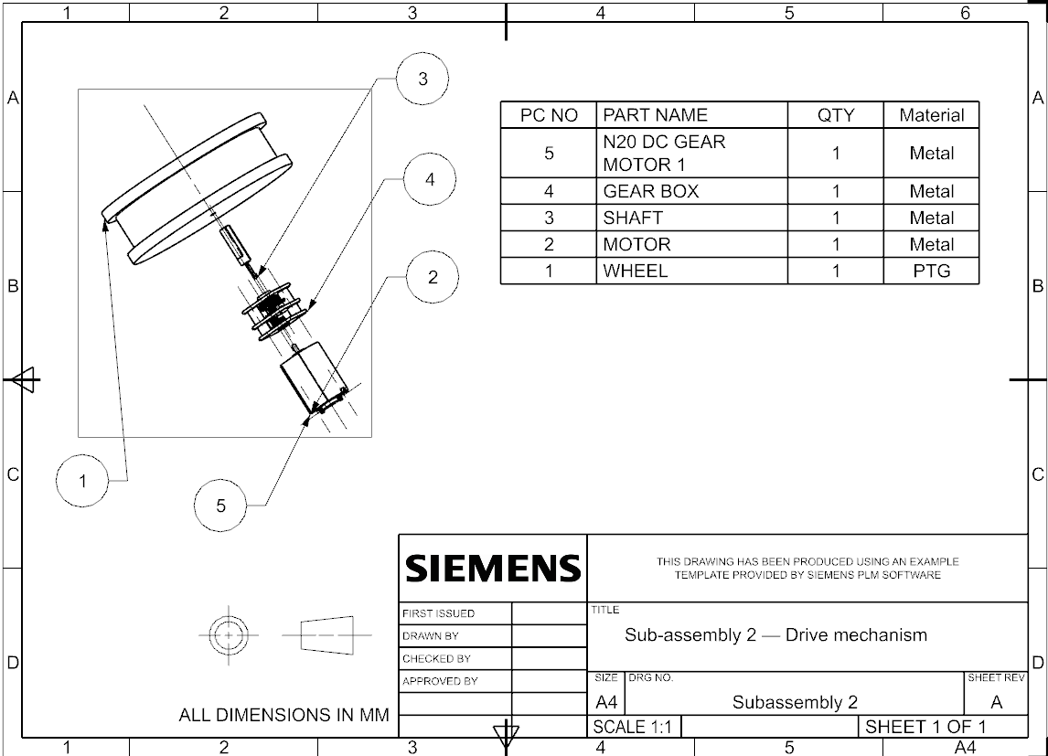
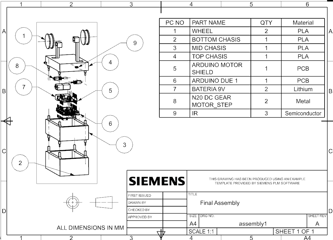
After scoring five drive concepts in a weighted Pugh matrix, a dual-wheel friction drive was selected. The two motor-driven wheels rest on top of the rope so the carriage's own weight supplies the normal force for traction, removing the need for a separate clamping mechanism and keeping the design light and simple. The chassis was modelled in Siemens NX as a three-tier stack and 3D printed in PLA.
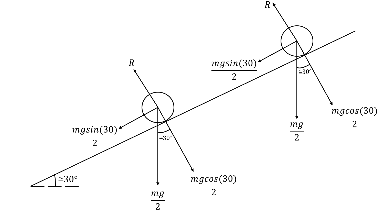
A free-body analysis of the carriage on the 30° incline set the traction targets. The climbing force needed is mg·sin(30°), while each wheel's grip depends on the normal reaction mg·cos(30°)/2. Setting friction equal to the climbing demand gives a required coefficient of μ ≈ tan(30°)/2 ≈ 0.289 — comfortably within reach of the wheel-on-rope interface.
Speed and timing followed from the 75 rpm motors and 25 mm wheel radius, giving roughly 0.20 m/s along the 3.66 m round-trip path. Centre-of-mass and sensor-placement studies kept the masses low and symmetric for stability, and positioned the IR sensors clear of the rope to avoid false readings.
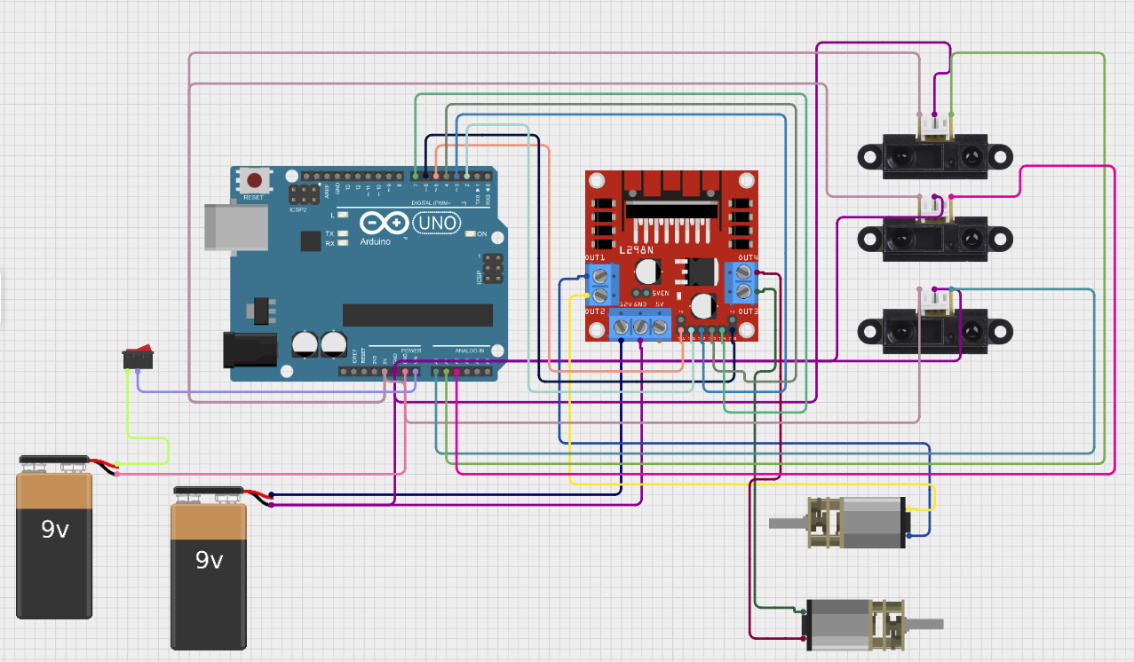
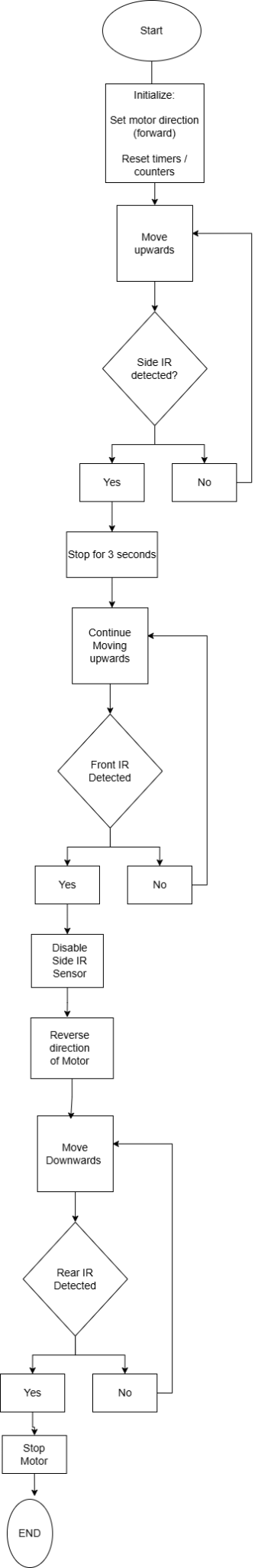
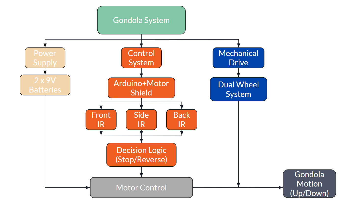
The system breaks into three subsystems — power, control, and mechanical drive. An Arduino paired with a motor shield reads three IR reflectance sensors and runs a state machine that drives the carriage forward, pauses at each detected tape marker, holds 7 seconds at the top, then reverses home.
A 50 ms debounce filter on the side sensor rejects false positives and caps intermediate stops at two, while front and back sensors define the top and home limits. A Safety FMEA flagged battery voltage drop, missed tape detection, and wheel slip as the highest-priority risks, each addressed during testing.
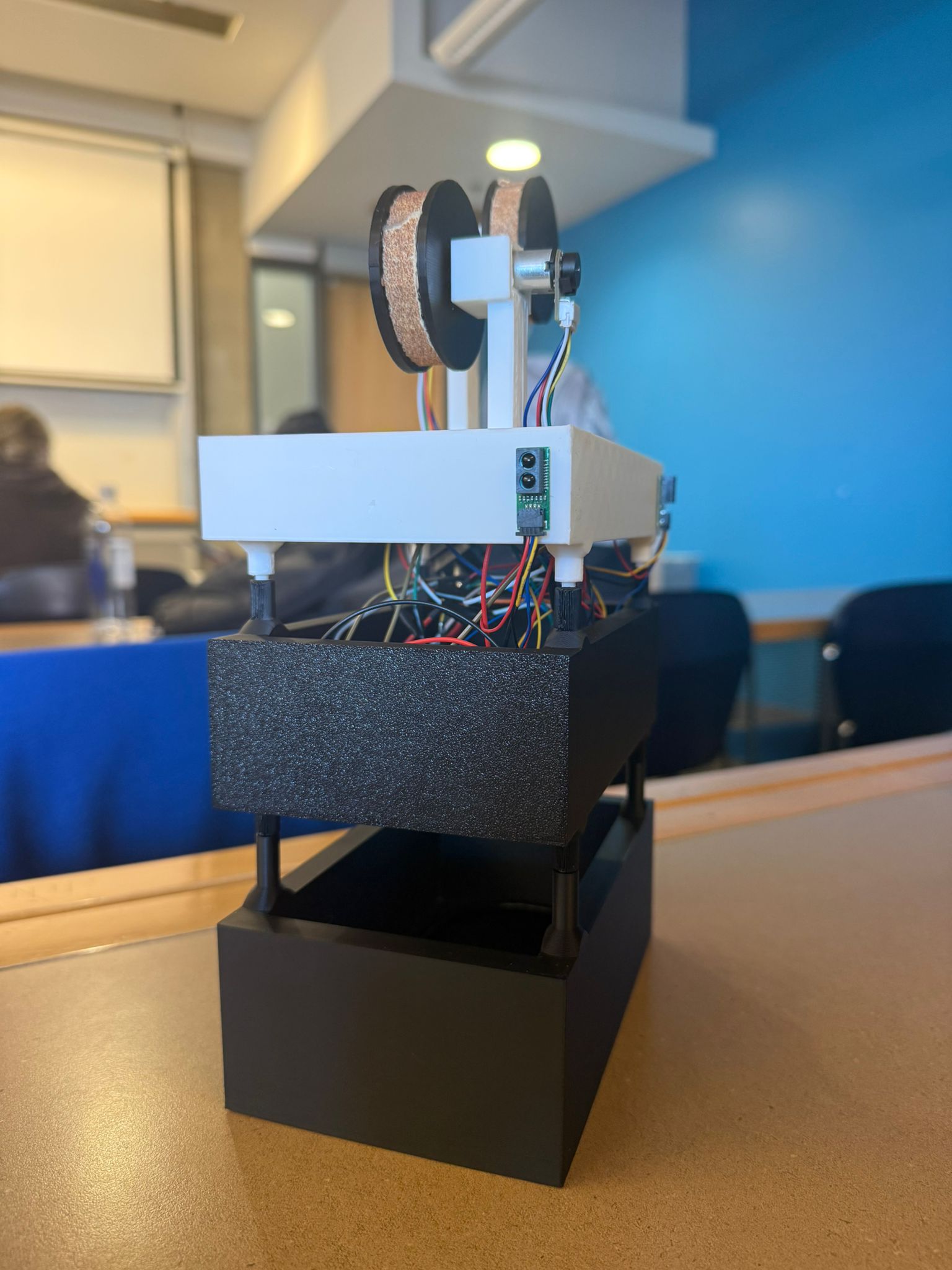
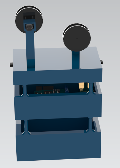
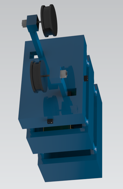
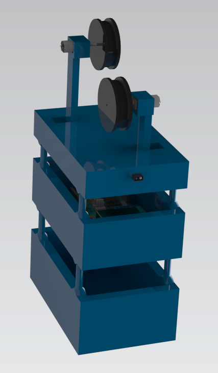
The final build closely follows the CAD model: a three-tier 3D-printed PLA chassis, with the drive wheels wrapped in friction tape to grip the rope, an N20 gear motor on the printed pillar mount, and an IR reflectance sensor set into the upper tier. The Arduino, motor shield, and 9V batteries sit in the lower tiers, with the wiring routed between levels.
On the demo rig it completed the full autonomous round trip — climbing the incline, pausing at the tape markers, holding at the top, and returning home — without losing traction or dropping a passenger.